Harika Mark-1 CubeSat Structural Design

Gallery
Context & Problem
The SS AMU SAT team at Aligarh Muslim University needed a 3U CubeSat chassis for an IN-SPACe-approved mission launching on ISRO's PSLV. The structure had to survive 12g launch loads, comply with the Cal Poly CDS standard and P-POD deployer interface, weigh under 4 kg total, and critically for a student team, be affordable and easy to service when subsystem boards inevitably needed debugging.
My Role
As Mechanical Lead, I managed a team of 8 students and owned the full structural design pipeline: problem scoping, CAD modelling in Fusion 360, material selection, manufacturing method selection, FEA campaign in ANSYS (static + modal), and iterating the design through multiple fabrication attempts. I also co-authored the IEEE SPACE 2025 paper documenting the design and analysis.
Design Decisions
RAM-style modular PCB layout
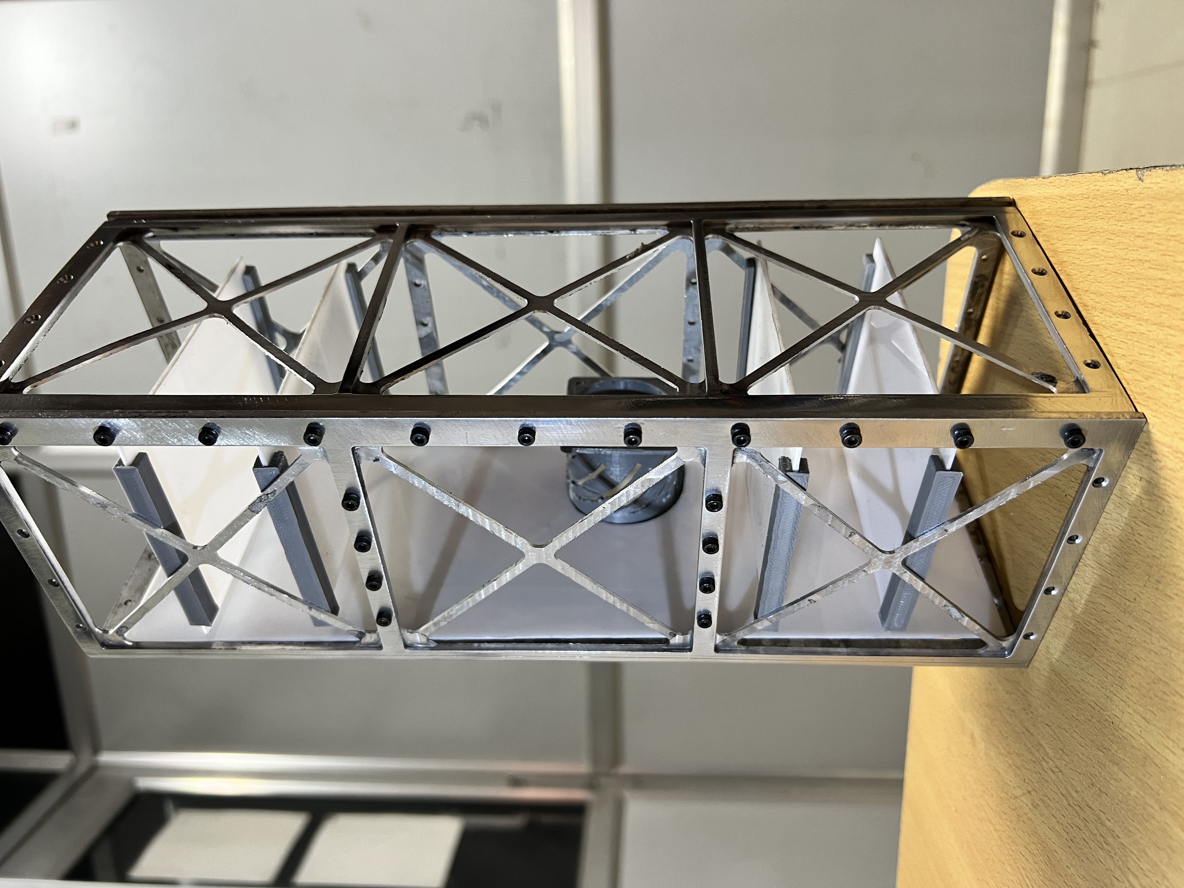
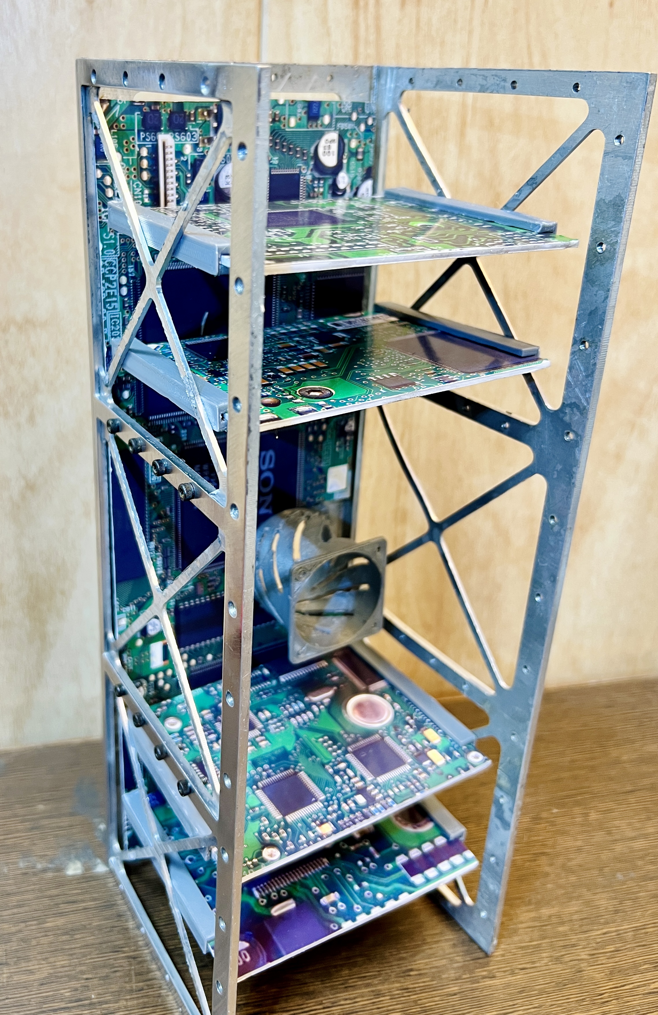
Traditional CubeSats stack boards on top of each other. To access a middle board, you have to disassemble the entire stack. I designed the chassis so a single motherboard runs longitudinally along the length, and up to 8 subsystem daughter cards slot in perpendicular to it, locking into machined guide rails like computer RAM. This means any individual subsystem card can be pulled out and replaced independently without disturbing the rest of the satellite. This was a huge time-saver during integration and debugging.
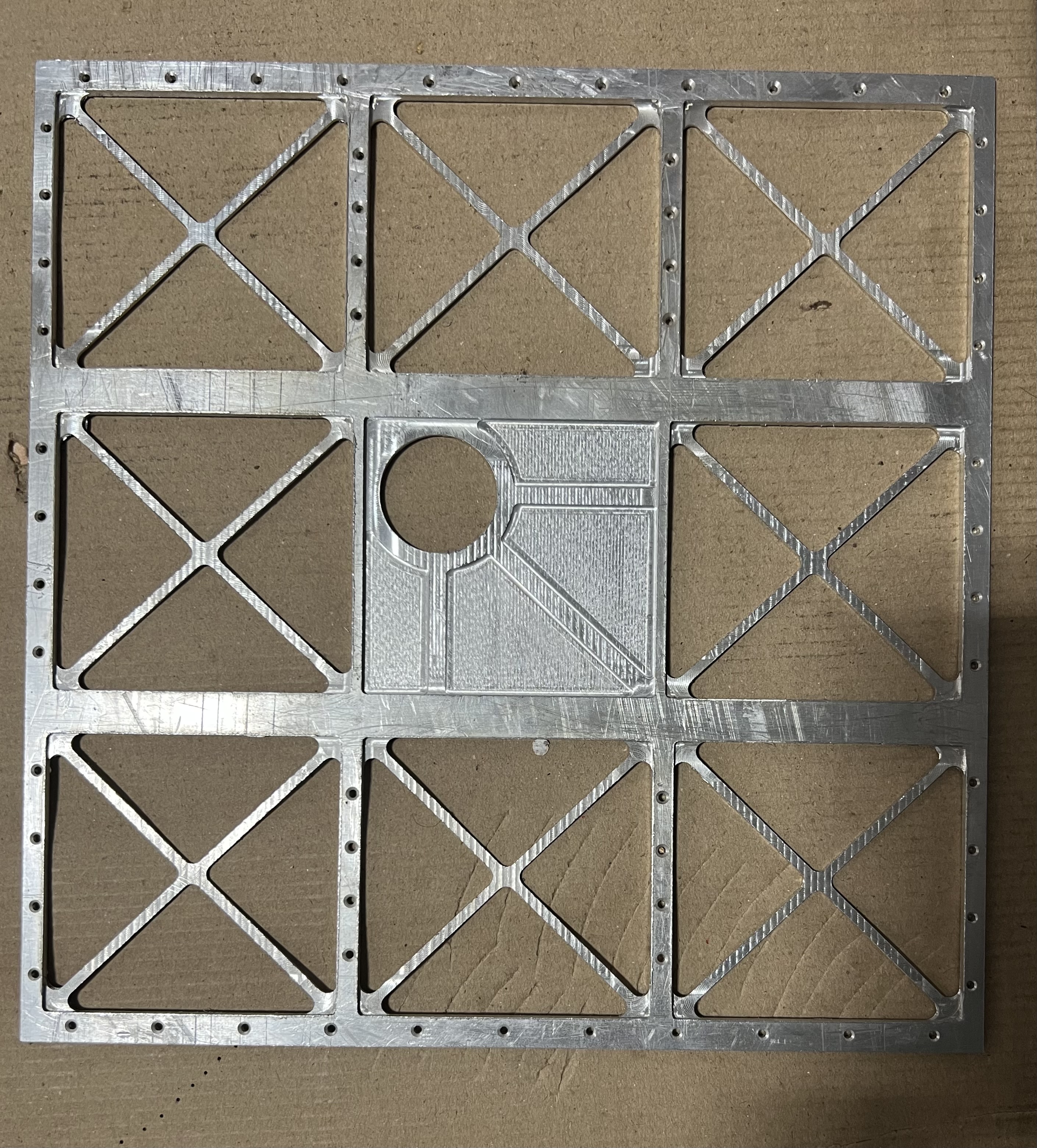
Monolithic chassis from a single Al-7075 billet
Rather than assembling the frame from multiple plates and fasteners, the entire chassis is machined from one block of aluminium. This eliminates 40+ potential fastener failure points, raises the natural frequency (critical for surviving PSLV vibration), and reduces mass. The trade-off is higher per-unit machining cost, but for a student mission building one satellite, the reliability gain far outweighs the cost difference.
Al 7075-T6 over Al 6061
Both are NASA-approved for CubeSat structures. I chose 7075-T6 for its higher yield strength (503 MPa vs 276 MPa), which gave more structural margin under the monolithic design's thinner wall sections. The trade-off is slightly lower machinability and weldability, but since the monolithic design eliminates welding entirely, this wasn't a penalty.
Deployable solar panels with thermo-cutter release
Power budget calculations showed body-mounted panels alone couldn't meet the mission's power requirements. I designed hinged deployable panels that fold flat against the rails for launch (held by a fishing line), then deploy via a thermo-cutter. It's a simple, reliable mechanism with no moving parts beyond the hinge.
Iterate & Improve
From sheet metal to monolithic: a failed prototype that improved the design
Our first approach was to CNC-machine a flat sheet of Al-7075 and then bend it into a cuboid. This would have been significantly cheaper than machining from a solid billet. We fabricated a prototype, but the bend corners had unacceptable dimensional error. The inside radii were inconsistent, the faces weren't square, and the resulting chassis couldn't meet the ±0.1 mm tolerance required by the Cal Poly CDS for the P-POD interface. Rather than trying to salvage the sheet metal approach with tooling corrections, I pivoted to machining the entire chassis from a single billet using wire-cut EDM. This was more expensive per unit, but it gave us sub-0.05 mm tolerance on all critical interfaces, eliminated the bend-radius problem entirely, and as an unexpected benefit, produced a stiffer structure with higher natural frequencies than the sheet metal version would have achieved.
Analysis & Results
- Static FEA (ANSYS, 102,963 tetrahedral elements): peak von Mises stress of 4.7 MPa under 250N load (12g x 1.5 safety factor x 2 P-POD factor). That's just 0.9% of the 503 MPa yield strength of Al 7075-T6.
- Peak deflection of 0.0078 mm. Essentially zero deformation risk to internal subsystems.
- Modal analysis: first natural frequency at 270.11 Hz, 3× higher than the PSLV minimum requirement of 90 Hz, confirming the monolithic design's stiffness advantage.
- Combined NASA GEVS load calculation (longitudinal + lateral + random vibration): structure survives 38g combined worst-case loading.
- Frame mass of 0.645 kg. Roughly 15% lighter than equivalent fastened multi-plate designs while being ~25% stiffer.
What I'd Improve Next
- Add thermal analysis. Temperature-induced stresses during orbital cycling could affect long-term structural integrity but weren't modeled in this study.
- Investigate radiation and micro-meteoroid degradation effects on Al 7075-T6 over mission lifetime.
- Explore composite or Al-SiC alternatives for further mass reduction while maintaining stiffness.
- Include P-POD enclosure contact effects in FEA for more accurate boundary conditions.